Tuesday, October 12, 2010

"Network Topology"
Network topology is the layout pattern of interconnections of the various elements (links, nodes, etc.) of a computer network.[1][2] Network topologies may be physical or logical. Physical topology means the physical design of a network including the devices, location and cable installation. Logical topology refers to how data is actually transferred in a network as opposed to its physical design.
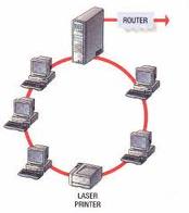
Topology can be considered as a virtual shape or structure of a network. This shape does not correspond to the actual physical design of the devices on the computer network. The computers on a home network can be arranged in a circle but it does not necessarily mean that it represents a ring topology.
Any particular network topology is determined only by the graphical mapping of the configuration of physical and/or logical connections between nodes. The study of network topology uses graph theory. Distances between nodes, physical interconnections, transmission rates, and/or signal types may differ in two networks and yet their topologies may be identical.
A local area network (LAN) is one example of a network that exhibits both a physical topology and a logical topology. Any given node in the LAN has one or more links to one or more nodes in the network and the mapping of these links and nodes in a graph results in a geometric shape that may be used to describe the physical topology of the network. Likewise, the mapping of the data flow between the nodes in the network determines the logical topology of the network. The physical and logical topologies may or may not be identical in any particular network.
"Star Topology"
Star networks are one of the most common computer network topologies. In its simplest form, a star network consists of one central switch, hub or computer, which acts as a conduit to transmit messages.[1] Thus, the hub and leaf nodes, and the transmission lines between them, form a graph with the topology of a star. If the central node is passive, the originating node must be able to tolerate the reception of an echo of its own transmission, delayed by the two-way transmission time (i.e. to and from the central node) plus any delay generated in the central node. An active star network has an active central node that usually has the means to prevent echo-related problems.
The star topology reduces the chance of network failure by connecting all of the systems to a central node. When applied to a bus-based network, this central hub rebroadcasts all transmissions received from any peripheral node to all peripheral nodes on the network, sometimes including the originating node. All peripheral nodes may thus communicate with all others by transmitting to, and receiving from, the central node only. The failure of a transmission line linking any peripheral node to the central node will result in the isolation of that peripheral node from all others, but the rest of the systems will be unaffected. [2]
It is also designed with each node (file servers, workstations, and peripherals) connected directly to a central network hub, switch, or concentrato
"Tree Topology"
Among all the Network Topologies we can derive that the Tree Topology is a combination of the bus and the Star Topology. The tree like structure allows you to have many servers on the network and you can branch out the network in many ways. This is particularly helpful for colleges, universities and schools so that each of the branches can identify the relevant systems in their own network and yet connect to the big network in some way.
"Bus Topology"
A bus network topology is a network architecture in which a set of clients are connected via a shared communications line, called a bus. There are several common instances of the bus architecture, including one in the motherboard of most computers, and those in some versions of Ethernet networks.
Bus networks are the simplest way to connect multiple clients, but may have problems when two clients want to transmit at the same time on the same bus. Thus systems which use bus network architectures normally have some scheme of collision handling or collision avoidance for communication on the bus, quite often using Carrier Sense Multiple Access or the presence of a bus master which controls access to the shared bus resource.
A true bus network is passive – the computers on the bus simply listen for a signal; they are not responsible for moving the signal along. However, many active architectures can also be described as a "bus", as they provide the same logical functions as a passive bus; for example, switched Ethernet can still be regarded as a logical network, if not a physical one. Indeed, the hardware may be abstracted away completely in the case of a software bus.
With the dominance of switched Ethernet over passive Ethernet, passive bus networks are uncommon in wired networks. However, almost all current wireless networks can be viewed as examples of passive bus networks, with radio propagation serving as the shared passive medium.
The bus topology makes the addition of new devices straightforward. The term used to describe clients is station or workstation in this type of network. Bus network topology uses a broadcast channel which means that all attached stations can hear every transmission and all stations have equal priority in using the network to transmit[1] data.
The Ethernet bus topology works like a big telephone party line — before any device can send a packet, devices on the bus must first determine that no other device is sending a packet on the cable. When a device sends its packet out over the bus, every other network card on the bus sees and reads the packet. Ethernet’s scheme of having devices communicate like they were in chat room is called Carrier Sense Multiple Access/ Collision Detection (CSMA/CD). Sometimes two cards talk (send packets) at the same time. This creates a collision, and the cards themselves arbitrate to decide which one will resend its packet first. All PCs on a bus network share a common wire, which also means they share the data transfer capacity of that wire – or, in tech terms, they share its bandwidth.
This creates an interesting effect. Ten PCs chatting on a bus each get to use a much higher proportion of its total bandwidth than, for instance, 100 PCs on the same bus (in this case, one – tenth compared to one – hundredth). The more PCs on a bus, the more likely you’ll have a communication traffic jam. [2]
"Ring Topology"
A ring network is a network topology in which each node connects to exactly two other nodes, forming a single continuous pathway for signals through each node - a ring. Data travels from node to node, with each node along the way handling every packet.
Because a ring topology provides only one pathway between any two nodes, ring networks may be disrupted by the failure of a single link[1]. A node failure or cable break might isolate every node attached to the ring. FDDI networks overcome this vulnerability by sending data on a clockwise and a counterclockwise ring: in the event of a break data is wrapped back onto the complementary ring before it reaches the end of the cable, maintaining a path to every node along the resulting "C-Ring". 802.5 networks -- also known as IBM Token Ring networks -- avoid the weakness of a ring topology altogether: they actually use a star topology at the physical layer and a Multistation Access Unit (MAU) to imitate a ring at the datalink layer.
       " Mesh Topology "

Mesh networking is a type of networking wherein each node in the network may act as an independent router, regardless of whether it is connected to another network or not. It allows for continuous connections and reconfiguration around broken or blocked paths by “hopping” from node to node until the destination is reached. A mesh network whose nodes are all connected to each other is a fully connected network. Mesh networks differ from other networks in that the component parts can all connect to each other via multiple hops, and they generally are not mobile. Mesh networks can be seen as one type of ad hoc network. Mobile ad hoc networks (MANET) and mesh networks are therefore closely related, but MANET also have to deal with the problems introduced by the mobility of the nodes. Mesh networks are self-healing: the network can still operate when one node breaks down or a connection goes bad. As a result, the network may typically be very reliable, as there is often more than one path between a source and a destination in the network. Although mostly used in wireless scenarios, this concept is also applicable to wired networks and software interaction. The animation at the right illustrates how wireless mesh networks can self form and self heal. For more animations see History of Wireless Mesh Networking

Basicon

Prelim
"Charles Babbage"
*Called the "Father of computing"
*Invented the analytical and difference Engines.
*Born on December,26,1791 in the uk.